| PTCR GENERAL: |
|
PTCR (Positive Temperature Coefficient of Resistance) is a kind of positive temperature coefficient thermistor which is mainly made up of BaTiO3 ceramics. BaTiO3 ceramics is a kind of typical ferroelectric material with the resistivity of greater than 1012Ω cm under normal temperature, through semiconductor doping it has a strong PTC efficacy——it has extremely low resistance under normal temperature but it experiences a sudden and large mutation around Reference temperature as ambient temperature rises. It is because a barrier layer induced by the surface state exists on the crystal particle border of the multicrystal BaTiO3 semiconductor material. Under Curie temperature, the high-resistance crystal boundary has ferroelectric characteristics with great dielectric constant and low potential barrier, electrons can easily penetrate the potential barrier and corresponding materials have low resistivity. When above Curie temperature, crystal lattice occurs at the high-resistance layer and the ferroelectric constant decreases quickly. The potential barrier increases because the dielectric constant drops in accordance with the Curie-Weiss Law. With the dramatic increase of the barrier height, it becomes difficult for electrons to pass potential barrier and resistivity of the corresponding materials rises dramatically. This behaves as the PTC efficacy of the material in a macro manner. Due to this property, the PTC thermistor is widely used both on industrial electronic equipment and household appliances. The field of its application can be classified in light of three basic electric performances of the PTC thermistor. The fundamental parameters are indicated in the following diagram.
|
TC: Curie Temperature (resistance rises sharply)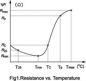
Tmax: Max. Temperature (at this temperature the Zero-power is maximun)
T-p: Poise point temperature
Tmin: Min.temperature (at this temperature the zero-power resistance is minimum)
T25: Room temperature 25℃
RC: Switch resistance value Rc=2Rmin
Rmax:The Max. Resistance that PTCR can get
Rp: Poise point resistance
Rmin: Min. zero-power resistance
R25: Resistance at room temperature(25℃)
|
| PTCR COMMON GLOSSARY : |
Rated Zero-power
(Rn) |
DC resistance value of the thermistor measured under 25℃by adopting sufficiently low power consumption. |
|
Maximum Operating
Voltage (Vmax) |
The maximum rated voltage the PTC thermistor can continuously endure at 25℃. |
Maximum Inrush Current
(imax) |
The maximum current (effective value) through the PTC thermistor under maximum rated voltage. Exceeding this current may result in the damage to the PTC components. |
Reference temperature
(Tc) |
The temperature at which the resistance value of the PTC thermistor increases to twice Rmin, also called switch temperature. |
Non-trip current
(Ih) |
Rated current or holding current, at maximum operating temperature, this is the current value that doesn't trip the PTC to the high resistance state. Under these conditions , PTC performs as a fixed resistor. |
Trip current
(It) |
The current value that will cause the PTC to trip to the high resistance state. |
Operating Temperature
Range
|
The ambient temperature range in which PTC can be used when the maximum voltage is applied. Range from -10℃to +60℃. |
Temperature Coefficient of
Resistance(αT ) |
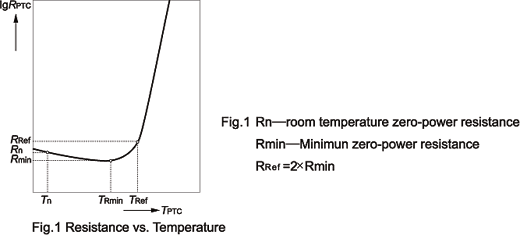
The temperature coefficient is calculated from the linear range at the steepest portion of resistance (Tp-Tb) as illustrated in fig.1.
(αT )=(lnRp-lnRb)·100/(Tp-Tb)(%/℃) |
|
| |
| PTC CHARACTERISTIC: |
|
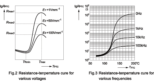
Resistance-temperature characteristic means the relation of zero-power resistance of PTC thermistor body temperature under a specified voltage shown in Fig.1. Zero-power resistance should be measured in super slot by using pulse power supply with low output impedance and stable output amplitude. Temperature rise of PTC thermistor induced by measuring current should be limited that it could be ignored. Shown in fig. 2、3 are resistance-temperature characteristic curves for various voltages and frequencies. As shown in fig. 2、3, at the same temperature resistance value decreases dramatically as measuring voltage and voltage frequency increase.
|
 |
 |
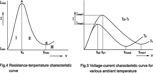
| Voltage-current characteristic normally means the relation of voltage across PTC thermistor to current under stable condition with thermal balance in static air of 25℃, that is ,voltage-current characteristic of PTC thermistor in actual operating state as shown in Fig.4. Ⅰstands for non-operating area or linear area , Ⅱ stands for jumping area, Ⅲ for breakdown area. When measuring the characteristic, ambient temperature should be kept constant and current readings should be taken after thermistor body temperature is balanced, and measuring circuit is shown in Fig.6. Fig.5 are voltage-current characteristic curves for various ambient temperatures of PTC thermistor.
|
 |
 |
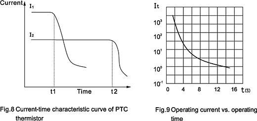
| Current-time characteristic means current change characteristic vs. time(as shown in Fig.8). It is normally measured with memory oscilloscope by using measuring circuit as shown in Fig.7.
Shown in Fig.9. is the relation curve of operating current to operating time. Operating time of PTC thermistor decreases dramatically as initial current increases. Furthermore the operating time is related to resistance temperature coefficient, applied voltage and heat capacity of PTC thermistor.
|
 |
| |

